RTX 3090 High GDDR6X RAM Temperatures of 110deg C

TransAmDan

Forum Admin
Staff member
Creating a new thread for my interest in mining with the RTX3090. This thread will be useful for other people doing the same as me, people will search and find this thread.

Both the RTX3080 and 3090 GFX cards from Nvidia have temperature monitoring on the DDR6X RAM chips. These chips run extremely fast, and taking a lot of power. they are clocking at 2500Mhz, and are quad data rate chips so effectively working at 10Ghz. There are 24GB of these chips on the board, spread across both sides of the PCB (RTX3090), only 10Gb on the 3080.
When they get too warm the GPU throttles back to protect things. The thing is their operating temperatures are 95degC, and people have seen them up to 110deg C. You can underclock the RAM to keep it a little cooler.

How do we know the temperature of the RAM chips? Well using HWINFO64 it is a very useful tool. It is free, and lets you analyse soo many parts of the PC in detail.
HWInfo_RTX3090_high_tempratures.png

This is too high for my liking. GPU is working pretty much flat out and that's only 40deg C (12degC room temperature). If I can get the ram chips down to 60degC I would be well happy.

So where are the RAM chips located?
On the side of the board around the GPU, the 12 unlabelled squares. These chare the same large heatsink as the GPU, so shouldn't be the issue, unless the thermal pads to the heatsink are not great.
Power-Scheme-Front-2.jpg

There are also 12 RAM chips on the rear. these have thermal pads to the back plate. There is no real heatsinking on these part from the backplate.
Power-Scheme-Back-1.jpg


What temperature do we see on the backplate?
RTX3090_Rear_Plate_Temperature.jpg

So almost 60degrees on the backplate. Why so low? Why do we see 100 on the chips? Perhaps we are loosing 40degrees in the thermal conductivity to the pads. This could be improved by using thinner thermal pads. I'm sure it can be improved. there is no real heatsinking on the back plate. A bit of an oversight in the design.

geforce-rtx-3090-shop-630-d.png

Thinking of removing the black back cover. Replacing it with a solid 3mm thick sheet, may need to use spacers to get it in the right position. Then I'll screw on a 100x100mm heatsink, countersunk and flat on the inside. The screws wont be on top of the RAM chips, want to keep this part as flat as possible.
RTX3090_New_Heatsink.jpg


The current back cover does have heat transfer pads. I don't know how thick they are, but there could be room for improvement here.

Backplate-1.jpg


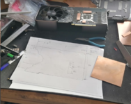
So below is my plan.
Black heatsink, joined to the 3mm thick copper sheet. Then raised copper pads that the thermal pads sit on. The reason for the raised copper bits is that there are other components under the back cover that are higher than the RAM, like SMT capacitors, so the back cover will be resting on them.

RTX3090_Rear_Heatsink_Side.jpg


I should get all the parts this week, so will be attacking this at the weekend. I'll get many photos during the creation.
 
I know it can be messy stuff, but would heatsink compound conduct the heat away from the chips and into the heatsink any better than the heat transfer pads? Or isn't that really an option?
It works well for high power transistors. The factory used it in the assembly of our 250w and 500w audio power amps when bolting them to their heatsinks.
Yes, I have some of that coming.
I think part of the issue is the backplate is totally flat, there are some capacitors, say 4mm high that the heatsink covers, and the hot parts are the ram chips, these may only be 2mm high. So they have used a thick heat transfer pads to bridge the gap, instead of machining the heatsink to recess around the capacitors. Machining is costly I guess.
So what I plan to do it use a flat peice of 3mm thick copper, and raise certain parts of it with 1mm thick copper glued on with heatsink glue. Then bridge the remaining gap with heat transfer pads. Then on the outside join the large heatsink to the copper using the heate transfer paste and screws.
Its going to be a much better improvement over the initial design.
A few other people have just glued heatsinks onto the backplate which has helped. I want to go that extra mile to make a super job of it.
 
My view would be increase the airflow over and around them. Fire it up and use something to monitor the airflow (smoke?) over the chips and ensure that fan is doing more than look pretty.

There is a real science to cooling. Even cars need their fans positioned just right in the shroud to be optimal.

Essentially the faster you can move the heat away from the chips the cooler they run. A heatsink can become heat soaked unless adequately cooled.
 
Good call, it all helps. My thinking was to first make sure you have the best possible heat transfer between the chips and heatsink, then you can work towards increasing airflow over the heatsink too. I will say that our amps cover both - by using heat sink compound on the power output devices as well as quad cooling fans fed by case intake and exit vents.
 
Remember, ducting can be used not only to direct air-flow but by introducing restrictions you can speed it up too.
Think Venturi in carburetters.
 
Added a fan ready for the heatsink. Temptatures 98 - 100degrees now, before is was flickering more between 100 and 102.

May need a bigger fan and getting it good for airflow like ducting etc...
1612279279807.png

Part of the problem is the heat is in the chip and not getting all to the backplate. So its really limiting to how much heat it can extract. Until I do this modification.
 
I have a day off on Friday. I plan to work on this. I'll remove one GFX card and start to make a heatsink. I have 3mm thick copper sheet, and some thinner pieces of copper sheet. I'll remove the covers and take some measurements of how high the RAM chips are compared to the GPU and capacitors. I will solder think strips of copper to the copper to the large sheet with a heat gun of flame torch. To be 0.5mm away from the memory chips and then insert the 1mm heat conducting foam. I plan to do this to both side of the board.

I'll take some photos along the way.
 
The Camaro costs money, these earn money, cooler it runs I can squeeze a little more power out of it.

I do have someone coming round soon to do a bit more welding under the Camaro. I may connect the fuel pipes up over the weekend. The new pump works.
 
What does the Camaro need £££ to be running?
I know you have front shocks to buy, perhaps with various suspension rubbers and fuel and coolant lines that have perished, but to get the car to fire?
 
What does the Camaro need £££ to be running?
I know you have front shocks to buy, perhaps with various suspension rubbers and fuel and coolant lines that have perished, but to get the car to fire?
Correct, no cost to get it to fire, apart from not earning from doing odd jobs.
 
Not earning? I thought you were furloughed?
You haven’t been made redundant have you?
Ah no. I'm at the same place working full time. At the end of March there are discussions about going back to 80% hours and 80% pay for ther next quarter. So I will probably have Mondays off as that is what the Irish office do.
I do some PCB design and firmware to do for another company in the evenings. So this takes away spare time, it helps pay for odd bits. So havn't really have much time to spend on the Camaro. Once these projects are done I will have my evenings back. I will have some hours at the weekend. Sarahs job dosn't sound too safe at the moment, so trying to prepare for things.
 
Had the day off work today. So started to make progress on this task.

I purchased 3mm thick sheet copper. Also got some 1mm and 2mm smaller sheets.
Brought some 1mm insulation plastic sheet.
M2.5mm tap
2mm drill bit.
M2.5 x 20mm screws.
100x100x25mm heatsink, https://uk.farnell.com/fischer-elektronik/sk-508-100-sa/led-heatsink-standard-extruded/dp/1850032
1mm thick thermal pad https://uk.farnell.com/laird-technologies/a15959-04/thermal-gap-filler-229-x-229mm/dp/2484739
2mm thick thermal pad https://uk.farnell.com/laird-technologies/a15959-08/thermal-gap-filler-229-x-229mm/dp/2484740
120mm 12V fan https://uk.farnell.com/multicomp/mc36277/fan-119mm-12vdc/dp/1924863

First task was to get the 3mm plate flat.
1613165680191.png


Card taken out of the rig, ready to take apart.
1613165732108.png


8 screws holding the cover on. 4 x phillips/pozi, and 4 x T5 (tiny star shaped)
1613165839284.png

The chips were a little damp, i guess this was the glue from the heatsink pads that are currently on the backplate.

1613165896537.png


Many thermal pads still on the cover
1613165950030.png


Using the cover as a template, a new copper back plate was cut.
1613166009144.png


Cut some 2mm thick copper for the DDR6X.
50mmx14mm, two of them
14x14mm
14x37mm
1613166055806.png


Creating a sketch as I go along. I'll get this drawn up and published on here. I also aim to make some more of this for my other RTX3090's
1613166169050.png


Using a blow torch I was able to solder these to the backplate. I did tin the copper first using regular colder and a heat gin.
1613166271302.png


Drilled and tapped hole in the heatsink, and created countersunk fixing holes for the plate to attached to the RTX3090. there is also heat sink compound between the heatsink and the backplate.
1613166336275.png


Adding the thermal pads, used the 1mm for the DDR, and 2mm elsewhere.
1613166410031.png


Then screw it together
1613166494014.png


1613166545088.png


Ready for power
1613166579314.png


Well booted up fine, and started mining right away. With this extra heatsinking I wondered how far I could push the over clocking. So raised it from +1000 to +1500 on the DDR6X ram clock.
1613166672986.png

Noticed the GPU is running slightly cooler too. Perhaps the pressing of the heatsink on the back is helping with conducting the heat.

With this over clocking I'm almost getting 126mh/s, the RTX3090 next to it is doing 120mh/s, as the over clocking is lower.
1613166787230.png


The RTX3090 that hasn't been modified is running hotter on the GPU. Nothing alarming. The ambient is arounds 14 degrees C. Just posting for comparison of an unmodified board in the same environment.
1613166843334.png


So the numbers were are interested in is the DDR6X ram temperature. Its been running for over an hours now.

Unmodified one that isn't overclocked as much is 104degrees
1613166973744.png


Modified and overclocked to the max. Only 86degrees. that's almost a 20 degree drop. Plus this is being overclocked far more.
1613167073994.png


I'd class that as a success.

Higher hash rate, lower temperatures. It will cope better when the ambient rises.

This is currently with an 80mm fan blowing over the heatsink. I have a 120mm fan to test next.
 

Attachments

  • 1613166138097.png
    1613166138097.png
    808.7 KB · Views: 10
Looks like quite a project..and a nice job. It must be rewarding to see the end benefits in the lower temperatures too! 👍
 
Looks like quite a project..and a nice job. It must be rewarding to see the end benefits in the lower temperatures too! 👍
Yes, very much so. Very rewarding. It took a long time, pretty much all day to create this. Half ay though thinking why did I start it, what if it never works again... all these concerning thoughts passing through. To see the results of a 20 degree drop was awesome. Keeping an eye on things, everything seems to be working perfect.
 
Last edited:
Temperatures still looking good, I can see the ambient temperatures rising, around 17 degrees now. The summer I'm sure it will get far hotter, so will be great to see how this heatsink performs.

There is certainly more visitors on this website, and most are viewing this page. Perhaps there are talks on other websites linking to here. People with the same card will be experiencing the same over heating as me and possibly looking for a solution. I must get the heatsink drawn up so other people can make the same thing if they wanted.
Hey Dan!

I literally joined the forum just so I could get a better look at your images! I would be *highly* interested in the drawings and dimensions you have. I may be able to have a friend mill it out of a block of copper.

Anything you'd change on your design?
 
Not into cars then doh shame on you lol. Sure Dan will be along soon
 
Back
Top